The resistance to positive wind pressure, negative wind pressure and torsion from dead load of stick constructions on curtain wall profiles is tested in a bending test according to DIN EN 16758. In combination with this, the breaking load of supports for infill supports such as glass supports is determined according to DIN EN 17146.
Glass supports and stick constructions are the most heavily loaded building components of a facade and must withstand enormous positive and negative wind pressure loads, high vertical loads due to dead loads and torsional forces due to load superimposition.
At the same time, stick constructions are important for the design of facades to enable the architecturally desired slim facade profiles. Dimensioning and structural verification are therefore of central significance in facade planning.
Why test?
Load tests according to DIN EN 16758 by a testing body accredited under building law are an ideal basis for reliably determining the limits of load-bearing capacity. The test results can be used optimally to calculate applications and design variants safely and economically, as well as to obtain recognition under building law.
In addition to the positive and negative wind pressure loads, the vertical load and the torsional stress caused by the dead load of the facade construction must also be taken into account. This is caused by the dead weight of the infillings, which is transmitted to the transoms via the glass supports.
To simulate a broad practical application, the load introduction can be varied in the bending test with a corresponding lever arm and tested until the component fails. The supports are loaded up to the maximum breaking force. In addition to the cause of failure, the design load is determined on the basis of the limit state of usability and the limit state of load-bearing capacity.
The results of the tests are an optimal basis for calculating further applications and design variants safely and economically. In addition, the ift test certificates also support coordination with the structural engineer and the application for national technical approval (NTA), approval of individual cases or project-related design approval.
Testable products
The tests can be carried out on the following products:
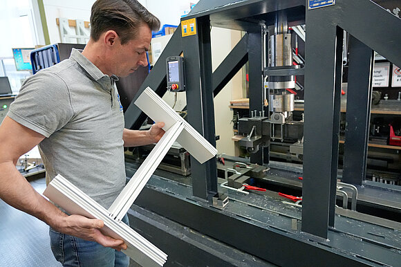
- Stick constructions/Transom-mullion-connections (e.g. tested on H or double H test specimens and special structures in coordination)
- Infill supports/Projecting supports (e.g. glass supports or filled infillings such as panels and special structures in coordination)
Test Sequence: Test of Stick Constructions as per DIN EN 16758
The same boundary conditions apply for each of the three testing methods listed below:
The test specimen series (5 pcs each) is loaded to failure using a tensile testing machine according to DIN EN ISO 7500-1 at room temperature (23+/-3)°C with a constant feed rate (path-controlled) at 5 mm/min.
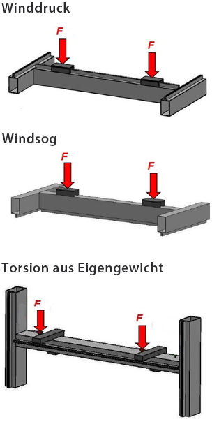
Positive and Negative Wind Pressure
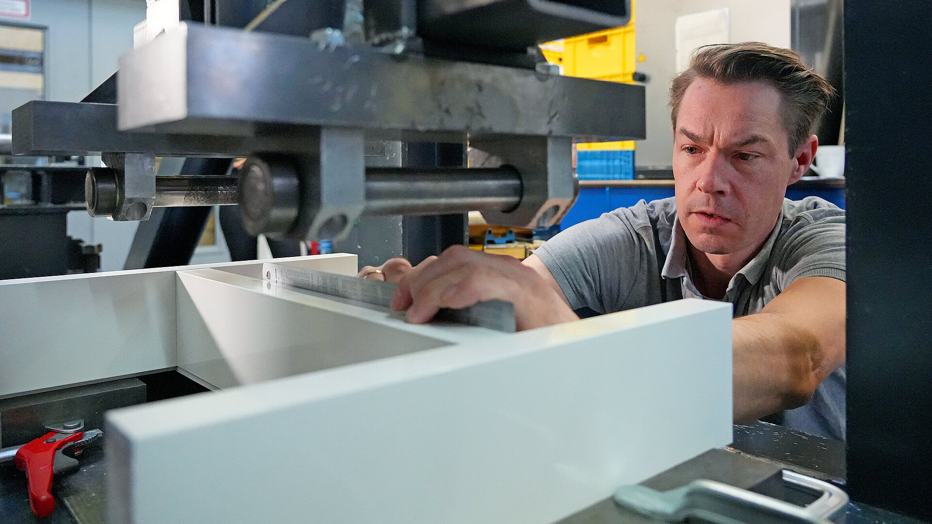
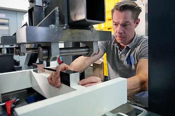
Installation is carried out in a horizontal position, both in the direction of positive and negative wind pressure. The test specimens are placed on two flat profiles over the entire length of the mullion and clamped in the outer area in each case. The force transmission takes place in the focus of the transom profiles and simulates a line load using a 4-point bending test.
Torsion from Dead Load
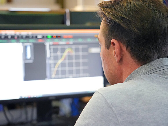
The installation is carried out in a vertical position. The test specimens are clamped in the upper area of the mullion. Care must be taken to ensure that clamping is as deformation-free as possible. The load is transferred to the transom via two steel profiles. The lever arm "e" and/or the load introduction can be selected variably. Very precise "displacement gauges" are used to accurately determine the deformation and lowering of the transom over the entire load application time.
Test Sequence: Testing a Support for Infillings as per DIN EN 17146
Vertical force transmission takes place by means of a "pressure blade". The lever arm "e" and/or the load introduction is determined according to the client's specifications.
In addition to determining the cause of failure at maximum force (breaking load), the design load is determined according to the normative methods described in Annex A - Limit state of usability, as well as Annex B - Limit state of load-bearing capacity.

Our Services after Completion of the Test of Stick Constructions and Infill Supports
- Regardless of the result, you will receive a detailed test report in German and English.
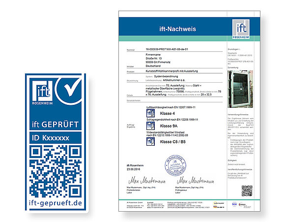
- If the implementation of tests is complete, you will also receive a concise ift-Nachweis in German and English.
- We provide support with the application for national technical approval, approval of individual cases or project-related design approval
- You will receive the ift-tested mark free of charge, with which you can market your products tested by ift Rosenheim effectively.
The advantages at a glance
Necessary for the test
- Required test specimens:
- Stick constructions / Transom-mullion-connections installed in a representative facade construction as H or double H test specimen
- Support for infillings installed on representative transom profiles
- Special constructions after coordination
- Required documents:
- Specimen drawings in dwg, dxf or tif format (view, horizontal and vertical sections) including all relevant dimensions
- If applicable, design overview for the selection of test specimens for possible system coverage by means of a subsequent expert statement
- Description of the test specimen (file will be provided when placing the order)
- Sampling report
Your Contact

Rolf Schnitzler

Dirk Köberle
