
Reading time: 1 minute
This technical contribution is based to a large extent on findings of the research project "Analyses regarding the feasibility of pressure released insulating glass units".
In the associated research report [1], differentiation is made between two types of pressure release of insulating glass units:
- The unique pressure adjustment to the local altitude of the installation location with con-
siderable difference in height between the installation location and place of manufacture: This subject is not elaborated here. Details are provided in the research report [1]. - Permanent pressure release of insulating glass units: This type of pressure release is the subject of this article.
Why can a durable pressure release be useful or even necessary?
The requirements for windows and facades e.g. regarding thermal insulation, solar shading and soundproofing are becoming more stringent. Thus, insulating glass units (IGU) with larger inter-pane cavities are becoming necessary.
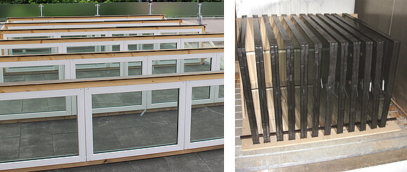
Conventional insulating glass units consist of several plane parallel glass panes, which are interconnected with the help of an edge sealing system. The resulting inter-pane cavities are hermetically sealed. This is necessary in order to keep the humidity of the air in the inter-pane cavities as low as possible and thus, to prevent the formation of condensation as well as the corrosion of evaporated metallic low-e coatings. Furthermore, the filling gas must be prevented from escaping.
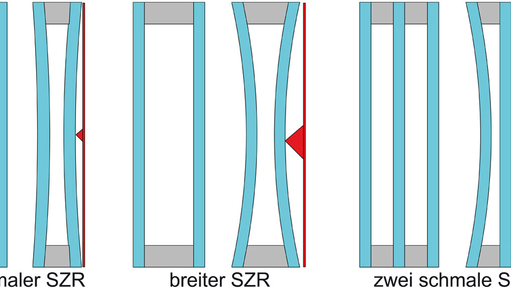
The disadvantage of hermetic sealing is that pressure equalisation between the inter-pane cavity and the surrounding atmosphere is prevented. If the air pressure or temperature in the inter-pane cavity changes, a pressure differential occurs between the inter-pane cavity and the atmosphere. The glass panes bulge in or out and are exposed to flexural tensions in the process. The edge seals are stressed by pressure or tension. The larger the inter-pane cavity, the more is the stress on the glass and the edge seals if the air pressure or temperature in the inter-pane cavity changes (Figure 1).

The potential impact of the high level of climatic impacts is the occurrence of optical distortions in reflection (pillowing), a jamming of the building components integrated into the inter-pane cavity such as e.g. solar shading systems, reduced durability of the edge seals (condensation in the inter-pane cavity) and – in extreme cases – breakage of the glass.
Pressure equalisation between the inter-pane cavity and the atmosphere would avoid high climatic impacts on the pane and the edge seals, and, thus, enable larger inter-pane cavities, with the help of which, in turn, the more stringent requirements for windows and facades could be met.
How can pressure release work in principle?
An opening in the edge seals would enable pressure equalisation between the inter-pane cavity and the atmosphere and, thus, relieve the panes and the edge seals. Instead of the development of pressure differentials between the inter-pane cavity and the atmosphere, flow rates would occur through the opening in the edge seals from the inside to the outside and vice versa. However, with complete pressure release (through a big opening in the edge seals), even plenty of moisture would enter into the inter-pane cavity via the flow rate and the durability of the insulating glass would be reduced to merely a few years.
Instead of complete pressure release, it is necessary to find a balance between pressure equalisation and moisture penetration. Thus, the pressure release can only be partial. The moisture penetration will be more than for hermetically sealed IGUs. However, the moisture penetration must remain so low that the amount of the desiccant that can be filled in the spacers is sufficient for the regular service life of an IGU, i.e. around 25 years.
A balance between pressure equalisation and moisture penetration can be achieved by restricting the air exchange between the inter-pane cavity and the atmosphere, e.g. with the help of capillaries or valves.
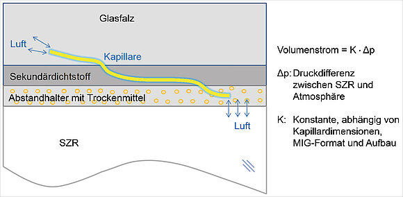
Figure 2 illustrates the principle of pressure release with the help of a capillary. This acts as a resistance to the flow and delays the exchange of air. The flow rate through the capillary is proportional to the pressure differential between the inter-pane cavity and the atmosphere, and, thus, it is available for calculation.
Capillaries are available in many varieties (inner diameter, length, metal, plastic) from laboratory suppliers. In most cases, they can be shaped easily and their resistance to flow can be adjusted by cutting them down in length. Diffusion of moisture through the capillary is negligible compared to the diffusion of moisture through a simple hole in the edge seals, since the concentration gradient in the capillary between the atmosphere and the inter-pane cavity is low based on the length of the capillary.
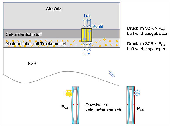
Figure 3 illustrates the principle of pressure release with the help of valves. In the neutral condition with planar and parallel glass panes, the valves are closed. If the temperature in the inter-pane cavity rises, the pressure in the inter-pane cavity will also rise until the outlet valve opens and the air gets blown out. When the pane cools down, the outlet valve closes, and the air in the inter-pane cavity contracts; a negative pressure develops and finally, the inlet valve opens and air is sucked in. The inter-pane cavity is sealed as long as the pressure in the inter-pane cavity remains between the inlet pressure and the outlet pressure of the valve. Changes in the outdoor atmospheric pressure, in principle, have the same effect as temperature changes in the inter-pane cavity. However, changes in the atmospheric pressure in the course of the day are normally considerably lower than changes in the temperature.
What needs to be observed for the technical implementation of durable pressure release?
For the technical implementation of durable pressure release of IGUs, among others, the following two issues need to be addressed:
- How can the durability of a pressure released IGU be tested or estimated?
- What are the capillary or valve parameters necessary in order to achieve an appropriate balance between pressure release and durability?
Is a durability test in accordance with EN 1279 useful?
Gas filling is not feasible with continuously pressure released IGUs since the gas would escape within a few weeks with the flow rates and diffusion. Thus, the gas leakage rate test in accordance with EN 1279-3 [2] is not applicable.
In conventional (hermetically sealed) IGUs, moisture is absorbed by the diffusion processes through the edge seals. In continuously pressure released IGUs, on the other hand, the mechanism of the moisture penetration primarily is the flow rate through the capillaries or the valves, and only secondarily the diffusion through the edge seals. The exact proportion of the diffusion with respect to the overall moisture penetration is not known. It is largely dependent on the manufacturing quality of the IGU. Based on the lower edge load – compared to the sealed IGU – the diffusion of moisture in pressure released IGUs, however, should be slower than in sealed IGUs.
Testing the moisture penetration according to EN 1279-2 [2] is based on the acquisition of diffusion processes. A small specimen size (resulting in high edge loads under exposure to climatic impact), high temperatures as well as a high concentration gradient (low humidity in the inter-pane cavity, high humidity outside) favour diffusion processes, especially during the high temperature / high moisture storage of the EN 1279-2 test. Flow rates between the atmosphere and the inter-pane cavity are not considered in the test according to EN 1279-2, and they should not occur at all in a hermetically sealed IGU.
If pressure released IGUs were to be exposed to high temperature / high moisture storage in accordance with EN 1279-2, the significant mechanism for moisture penetration during regular utilisation of a pressure released IGU, namely the flow rate through the capillaries or the valves, would practically not occur at all, since there are no temperature changes in the inter-pane cavity. Changes in atmospheric pressure during the high temperature / high moisture storage would only lead to low flow rates. The high temperature / high moisture storage of EN 1279-2 is basically not suitable physically to simulate ageing of pressure released IGUs.
Based on many years of experience we know that a conventional (hermetically sealed) system, which meets the requirements of EN 1279-2, most probably also meets the requirements for regular use over a time period of around 25 years. For continuously pressure released systems there is no such experience available. Based on the conformity with the requirements of EN 1279-2, you could infer that it is sufficiently durable. Testing the durability of continuously pressure released IGUs in accordance with the specifications of the product standard EN 1279-2, is, thus, physically not meaningful and not purposeful.
Calculation model for the estimation of pressure release and moisture penetration
Since (as explained in 4.1) verification of the durability in accordance with EN 1279-2 is not possible, a numeric calculation model has been developed with the help of which the moisture penetration as well as the degree of pressure release can be estimated.
Hourly weather data (temperature, solar irradiation, atmospheric pressure, atmospheric humidity) and parameters of the IGU (design, size, absorption characteristics) as well as parameters of the capillaries or valves are the input parameters for the calculations. First the temperature development in the inter-pane cavity is determined. Based on this and the changes in atmospheric pressure, the flow rates between the inter-pane cavity and the atmosphere are obtained. From the flow rate of air flowing into the inter-pane cavity and its relative humidity, the amount of moisture entering the inter-pane cavity is calculated. It is assumed that the moisture that has entered is absorbed completely by the desiccant.
Moreover, the degree of pressure release is determined – expressed as flexural tension in the panes and/or the pane deflection. An iterative process yields suitable capillary parameters (inner diameter, length) or valve parameters (inlet and outlet pressure), in order to reach a balance between pressure release and durability of the IGU.
The results of various model calculations
With the help of model calculations, some important correlations are meant to be illustrated as an example, and which are significant for the technical implementation of continuous pressure release.
The hourly weather data necessary for dynamic calculation was generated with the help of the software Meteonorm 7 [3].
Pressure release vs. moisture penetration
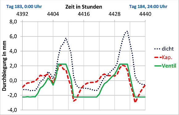
Figures 4a and 4b illustrate the pressure releasing effect of a capillary and a valve respectively. The x-axis in Figure 4a displays the hours of one year, from 12:00 am on 1 January until midnight on 31 December. The y-axis displays the mean deflection of an IGU pane. A positive value means outward bulging of the pane while a negative value means inward bulging of the pane.
The blue curve for the sealed IGU (Figure 4a) forms a belt, which, in principle, follows the seasonal changes of the outdoor temperature at the Rosenheim location. At the beginning of the year, there is a negative pressure in the IGU because it is colder than at the time of manufacturing the IGU, which is generally done at room temperature. Due to the negative pressure, the panes bulge towards the inside. In summer, it becomes warmer, the mean temperature in the inter-pane cavity rises and the panes bulge towards the outside. In winter, the temperature in the inter-pane cavity falls again, and the panes bulge again towards the inside. In principle, the amplitude of the belt reflects the daily course of the temperature.
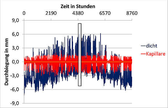
Size 1 m x 2 m, structure 6 - 80 - 6
Model calculation with climatic data pertaining to Rosenheim
a.) Chronological sequence of the pane deflection in the course of one year
(for the black frame, refer to b.)
The red curve for the IGU whose pressure is released with the help of a capillary (Figure 4a) forms a straight belt (no bow in summer due to high pane deflections). The belt is almost symmetrical with respect to the zero line and its amplitude is also smaller than the one of the blue belt. Thus, significant pressure release is achieved within the IGU with the help of the capillary.
Figure 4b illustrates a section of 4a, namely two days in July of that year. Near the curves for the sealed IGU and the IGU with capillary, you now also have a curve displayed for an IGU with valves. The valve parameters have been selected in such a way that the pressure release is approximately equivalent to that of the capillary. The plateaus just below the -2 mm deflection and just above the +2 mm deflection are noticeable on the green curve for the valve. These are the time periods in which the inlet or the outlet valve is opened respectively, i.e. where exchange of air between the inter-pane cavity and the atmosphere takes place.
Size 1 m x 2 m, structure 6 - 80 - 6
Model calculation with climatic data pertaining to Rosenheim
b.) Chronological sequence of the pane deflection in the course of two days in July
(section from a.), black frame)
Similar to Figure 4a, you can clearly see the effect of the pressure release. The deflections of the IGUs with capillaries or valves are significantly lower than the deflection of the sealed IGU.
Apart from the degree of pressure release (expressed in Figure 4 by the pane deflection), the moisture penetration also needs to be observed. The calculated values are shown in Table 1: around 18 gm/year for the IGU with a capillary and only 6 gm/year for the IGU with a valve. The moisture penetration via valves is relatively lower than the moisture penetration via a capillary with a ratio of 1:3. This ratio 1:3 (sometimes even 1:4) was also calculated for other sizes, structures and climatic zones. With a similar degree of pressure release, considerably less moisture penetrates into the inter-pane cavity than via the capillary.
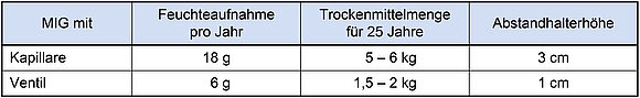
Size 1 m x 2 m, structure 6 - 80 - 6:
Moisture penetration per year as well as estimated values for
the amounts of desiccants for 25 years and the necessary spacer heights
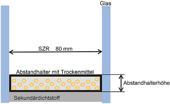
With respect to the technical implementation of pressure release of IGUs, the issue arises of the quantity of desiccant that should be filled into an IGU or the spacer height that would be necessary to penetrate this amount of desiccant to ensure the service life of the IGU for about 25 years. (Figure 5)
During a time period of 25 years a number of uncertainties occur. Only a very rough estimate is possible. The following route was adopted:
- Multiplying the values from the calculation model for the moisture penetration per year (18 gm/year for capillaries or 6 gm/year for valves, Table 1) with 25.
- Doubling the results from step 1, to consider climatic fluctuations and the diffusion through the edge seals.
- Calculation of the necessary amount of desiccant to absorb the quantity of moisture calculated in step 2, under the assumption of an initial loading of the desiccant of 3 % during the filling into the spacer and a saturation loading of 20 %.
- Calculation of the necessary spacer volumes or the necessary spacer heights, respectively (see Figure 5), to hold the necessary amount of desiccant calculated in step 3, under the assumption of an infill density of 0.65 g/cm3 for the desiccant
The results of the estimates are also listed in Table 1. As already mentioned, these values may only serve as a rough orientation, and are not yet meant for planning / development of specific pressure equalised systems.
Size 1 m x 2 m, structure 6 - 80 - 6
Model calculation with climatic data for the Rosenheim location, see Table 1
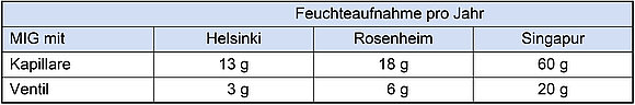
Similar degree of pressure release for all three locations.
Moisture penetration per year in different climatic zones
Impact of the location
To illustrate the impact of the climate on the moisture penetration of pressure released IGUs, the same calculations as those in 4.3.1 were made for Rosenheim and also for two other locations:
Cool region: Helsinki
Warm region with continuously high atmospheric humidity: Singapore
The results are displayed in Table 2.
The valves show significantly lower moisture penetration than for capillaries even for Helsinki and Singapore (ratio 1:4 for Helsinki and 1:3 for Singapore). You can clearly see the great impact of the climatic zone on the moisture penetration. Accordingly, e.g. in Singapore, three times more moisture penetrates than in Rosenheim. The advantage of the valves compared to capillaries in terms of moisture penetration would be particularly noticeable in Singapore with a lower quantity of desiccant.
Experimental investigations for the validation of the calculation model
Experimental investigations under conditions of outdoor weathering and in a climatic chamber were carried out in the course of the research project [1]. Since there were no suitable valves available during the project, only capillaries were used in the experimental investigations.
The experimental results conformed to the forecast of the calculation model to a great degree; especially with respect to the investigations done in the climatic chamber. There were some deviations with the test specimens used under conditions of outdoor weathering. Here, it must be considered that it is significantly more difficult to capture the exact stress conditions in outdoor weathering in order to incorporate them in the model calculations.
Conclusion
It is possible to have pressure release of insulating glass units with high durability at the same time.
Model calculations and experimental investigations have demonstrated that capillaries are suitable to achieve a balance between pressure equalisation and moisture penetration.
Valves proved to be very promising in the model calculations. With a similar degree of pressure release as in capillaries, they lead to a significantly lower moisture penetration.
There is no general solution. Structure, size, absorption behaviour, climatic conditions and capillary or valve parameters must be taken into consideration to reach an optimal combination of pressure release and durability.
ift Rosenheim is planning another research project. The pressure release with valves needs to be investigated in greater depth. Suitable valves must combine low operating pressures (few mbar) with high flow rates, long service life and freedom from maintenance. Ideally, the valves would be passive elements that work without any energy supply. However, even active, electrically operated and sensor-controlled elements may be necessary. The valves should not be obstructed in their function by dust particles, and no dust particles should enter the inter-pane cavity through the valves. ift would like to plan and execute the research project together with cooperation partners from the relevant sectors of the industry.
Acknowledgement
The contents of this article are based to a large extent on findings that were obtained in the course of the research project "Investigations regarding the implementation of pressure released insulating glass units" [1]. The project was promoted both financially and otherwise:
By the Federal Institute for Building, Urban and Space Research (Bundesinstitut für Bau-, Stadt- und Raumordnung) (File reference: SWD-10.08.18.7-12.12)
as well as by the industry partners:
- SANCO Isolierglasgruppe
represented by:
Sanco Beratung Glas Trösch GmbH, Nördlingen
Glas Müller Vetri, Bolzano
2. Finstral AG, Unterinn
The responsibility for the content of this articles remains with the author.
Literature
- Rose, A., Sack N.
Untersuchungen zur Umsetzbarkeit von druckentspanntem Mehrscheiben-Isolierglas
("Investigations regarding the implementation of pressure released insulating glass units")
Research report
ift Rosenheim 2015 - DIN EN 1279
Glas im Bauwesen – Mehrscheiben-Isolierglas
"Glass in building – Insulating glass units"
Beuth Verlag GmbH, Berlin - Meteonorm 7
Fa. Meteotest, Bern, Switzerland